


Single row angular contact ball bearing
Description
Design and Variations
The standard series of IMCB single row angular contact ball bearings 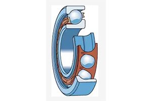 includes:
72 B (E) and 73 B (E) series bearings with a contact angle of 40 °
Some sizes of the 70B series
Sealed bearings:
Series 72B (E) (15 ≤ d ≤ 55mm)
Series 73 B (E) (12 ≤ d ≤ 50 mm)
The bearings in the 72 AC series have a contact angle of 25 ° (15 ≤ d ≤ 70 mm)
73 AC series bearings, 25 ° contact angle (17 ≤ d ≤ 70 mm)
Partial large size outer ring with flange
IMCB British bearings (ALS and AMS series)
Explorer bearings
Basic design bearings
Suitable for cross positioning configuration with only one bearing at each position, not suitable for pairing and installing two bearings directly adjacent to each other
The relative deviation between the width of the bearing and the inner and outer ring end faces is a common level tolerance
Compared to IMCB Explorer bearings, it has different performance
Universal matching bearings
Bearings that can provide contact angles of 25 ° and 40 °
Specially designed for paired use
The relative deviation between the bearing width and the inner and outer ring end faces is a precision tolerance
It can also be used in single bearing configurations to replace basic design bearings, as these bearings typically have higher precision and improve load-bearing capacity and speed
If two bearings are installed tightly against each other without using spacers or similar components, it is possible to achieve a predetermined clearance or preload or even distribution of load between the two bearings.
Universal paired bearings can be identified based on the following suffixes:
CA, CB, CC, or G represent bandgap
GA, GB, or GC indicate pre tensioning
When placing an order, you need to specify the required quantity of individual bearings, not the number of bearing groups.
Paired installation
Serial configuration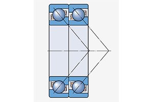
Used when the load-bearing capacity of a single bearing is insufficient
Average bearing of radial and axial loads
Parallel load lines
Can only withstand axial loads in one direction
If the axial load is applied in two directions, an additional bearing must be added that is counter paired with the series bearing group..
Back to back configuration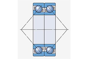
Bearing configuration with high rigidity
Can withstand overturning moment
Separate the load line from the bearing axis
Can withstand axial loads in two directions, but each bearing can only withstand axial loads in one direction
Face to face configuration 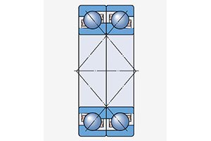
It can compensate for a certain degree of centering error, but it is not as rigid as a back-to-back configuration
The load line converges towards the bearing axis
Can withstand axial loads in two directions, but each bearing can only withstand axial loads in one direction
25 ° contact angle bearing (AC series)
The geometric shape of the raceway has been optimized and is suitable for high speeds
The axial bearing capacity is reduced, the compensation ability for center error is reduced, and it can withstand twice the impact load before generating edge stress
Make the optimized machined brass cage a standard configuration
Compared to bearings with a contact angle of 40 °, its advantages include:
Maximum speed increased by 20%
Improved radial load-bearing capacity (at the cost of reduced axial load-bearing capacity)
When using this type of bearing as a reverse non load bearing in a paired bearing that mainly bears axial loads in one direction, the reliability of the paired bearing can be improved

